Author: Frederick R. Vobbe, W8HDU
April 4, 2010
| Antenna 019: Inverted Dipole using Guy Wires Author: Frederick R. Vobbe, W8HDU April 4, 2010 |
This antenna was designed because I had a need for a 20 meter (14 MHz) antenna, but I couldn't find a way to fit it properly on the tower. The solution was to use the guy wires of the tower for the radiating elements. In doing this we must take into account some design features. First, the wired must be electrically independent from the tower. And since the wire is structural, it will have to be sized for the tension, and insulated.
You'll need a total of 16 of these. I don't recomend going on the cheap and using the minimum as a failure of one of the clamps could cause your tower to come down! I've always installed two, separated by four inches on the wire. Two will be used between the tower and the first insulator. Two will be used from the first insulator to the second insulator. Two will be used from the second insulator to the guy point on the ground. And the remaining two will be used for the ground attachment point. When you install the ones closest to the tower, wind in a #12 copper or short cut piece of wire that will be the jumper from the guy wire to the balun. Typically you can make this electrical connection on the third clamp closest to the tower, or the first clamp after the first insulator. See my picture below.
Again, starting at the tower we attach the guy cable, which winds around to the egg insulator with two clamps. After the first egg insulator we have two more clamps with the first one carrying a #12 jumper long enough to get to our balun on the side of the tower, (or hanging between the two guys). Further down the wire we have two clamps just before the second insulator. After the second insulator we have two more clamps. And finally we have two clamps where we attach to our ground mount. This antenna will have an impedance of around 27 ohms on 14.15 MHz, but don't let that scare you. You can use a 2:1 balun and feed the 2 side with 50-ohm coax, and the 1 side goes to the wires. If you feed it direct with 50-ohm cable, or a 1:1 balun, expect the match to be about 1.8 : 1. More later on this. To tune this antenna, install per the diagram but add a little more cable on the near side of the 2nd insulator. This allows you to lengthen the wire, and take up slack on the ground side of the guy. Take your measurements at 14.01, 14.1, 14.2 and so on. See where the dip in match is. If you're shooting for 14.230 MHz, and the match is better at 14.1 than any other part, you need to shorten the distance between the first and second insulator. If the match is better at 14.3 and awful at 14.1, then lengthen by a half inch at a time to walk it into the area you need. When making these changes, do both wires at the same time. Make sure the distance between the first insulator and the second is the same exact length. Start with a distance of 15.5 feet between the first insulator and the second. Depending on how critical your angles are for your guy wires, the number should slide around a bit. To make mine simple I used a 45 degree guy. This web site may help you in calculating wire lengths. So at this point you're probably wondering if it's worth the bother. YES it is. Here are some samples of the antenna pliots using EZNIC.   As you can see the pattern is somewhat skewed by the fact that you have two wires drooping, 120-degrees apart. For me, I have the major point of radiation pointed towards the south (180-degrees) and north (0-degrees). This works well for hurricane nets as well as hopping the pole. BUT... get creative for a moment. Suppose in the balun we also add SWITCHING. Suppose we could choose from guy wire 1 & 2, 2 & 3, or 3 & 1? Now we could have this patern rotate in 120-degree increments. So think about this when doing your construction. Finally, lets address the issue of the balun. This is no big deal. You can but 1:2 baluns from companies like Amidon Associates. Don't depend on them for any help. They only sell the products you need, but I have found them not to be too helpful with design questions. Instead, look for a copy of "Understanding, Building, and Using Baluns and Ununs" (Paperback) by Jerry Sevick (SK). I've seen used books for as little as $10, or new ones for $35.00. Once you understand how to make a balun you'll be very impressed with the results. If you just want to buy one, Buxcomm has their 2:1 Current Balun for $30.00. One quick thing, if you have more than one guy level, lower bands should go on top. That is, if you have a guy level at 45 feet, and one at 90 feet, the 40 meter would go on the top, and the 20 meter would go on the bottom. ALSO... if you are creative, you could also use traps in the guy wire so you could have 20/15 and 40/30 meter bands. However NEVER allow the trap to support the weight of the guy wire or tower. Wires should go to egg insulators with the trap connected across them. 73 & GUD DX |
 |
© Copyright 2008 All Rights Reserved - W8HDU |
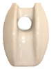 My 40 foot American tower uses a 3/16" guy wire. The wire is attached to the 32 foot level of the tower, As you would imagine, the two wires will not be perpendicular or end to end of each other. Guy wires are usually 3 wires spaced at 120 degrees from each other. Instead of the normal guy wire I used a pre-stretched cable available from T.S.C. The insulators are from MFJ, and they are p/n: MFJ-17A01 costing $2.10. For this project you'll need four insulators. Two at the feed, two at the end of the wire which will terminate into non-radiating support wires. You can use the same type wire, Phillystran, or transition to a different wire. Note, if you use another type of wire, make sure it's 3/16".
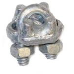 I use a cable clamp for the guy wire that looks like the one to the right. They are inexpensive, and the ones I use were from T.S.C. and were p/n 3551482 costing $.80 each (80 cents).