Author: Frederick R. Vobbe, W8HDU
October 10, 2010 (Updated 4/8/2012) Status: incomplete/on-going
| My Tascam M-3500 Console Reconstruction Project Author: Frederick R. Vobbe, W8HDU October 10, 2010 (Updated 4/8/2012) Status: incomplete/on-going |
|
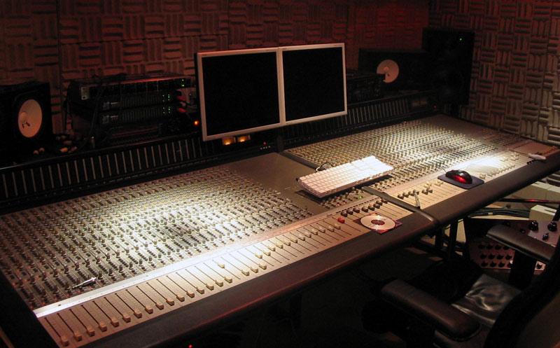
If you just found this page, please be patient as I'll be updating it only after I have performed the work and documented the results. If you don't see it here, then there is nothing more to tell you. This console was found in a production TV truck, and had about seventy actual hours on it. However, it had been sitting for over 13 years in a garage. Here in Ohio it can be -20 to 103 degrees, and humidity between 50 and 100%. Cosmetically the console is very nice. But the electronics will need some serious work! Like most Tascam/Teac products it was made to a minimum standard. By this I mean if the circuit calls for an opamp or capacitor, they put "something" in, but the component is not chosen for maximum quality. It's chosen for least expense for them. The console works, but it's noisy and frequency response is something to be desired. However, if you rework all the component flaws you have one heck of a console at a fraction of the price you would pay for something in the same size and feature! Typically a console like this goes for $350 to $1,250 depending on size and features. There is a 24 and 32 input version, as well as versions with full and partial meter bridges. I started finding much of my information from various musicians blogs, Google Groups, and GearSlutz. To save some time, you'll find PDF page captures of the various discussions. I also incorporated upgrades, mods, and additions due to my own skills in designing audio products. If you want to search for yourself use search terms such as Teac Tascam M-3500 M-3500 console mixer board audio in various configurations. Tools and Test Equipment: Potomac Instruments AA51, & AG51. Leader 1541C Oscilloscope. Leader 1311 Function Generator. Leader LDM-171 Distortion Meter. Heathkit IG5218 Sine/Square generator. Weller EC1002 solder pencil. My technician background; 45 years in radio and television broadcasting and high end studio audio, as well as electronics experimenter since age seven. Part 1 - Overview: The console I have is a Tascam M-3500, 32 input, with only the right half of the metering bridge. Not having the left half of the meter bridge, (an option), was a blessing for the modifications I wanted to make to this console. This project will be broken into several sub projects; cleanup and restoration, repair and restoration, and modifications. "Cleanup and restoration" refers to taking the board and power supply apart, cleaning all the surfaces and hardware, and then going through replacing dried up electrolytic capacitors and components that have failed. Electrolytic capacitors should all be changed if the board is older than fifteen years. When I opened the power supply up, the large electrolytic caps were already leaking, and smaller caps were bulged. This was from storage in an unheated garage for more than fifteen years. When in doubt, change the capacitors, and use only good quality capacitors rated for audio work. I say this only because a friend was restoring a Yamaha console and to cut his costs he purchased caps at a ham fest. I'm guessing the caps looked new, but were over a decade old. During a session, his console went up in smoke because all the caps let go in sort of a cascade effect. Buy new, fresh capacitors! The next phase will be "repair and restoration". This is where we go in and fix things we know are broken. Slider pots and switches often fall into this category. But you may find there are integrated circuits, (IC), that have died, open, shorted, or some other problem. Finally, modifications. This is where we make the console a little better than produced. Back in its day the M-3500 was a nice high end consumer console. Times have changed, and integrated circuits have become better. Reading some of the posts, (at the end of this page), will give you an idea of the results. Specifically in this rebuild I have several things on the agenda. The integrated circuits can be upgraded, and socketed. Capacitors can be upgraded. The inputs and outputs which are unbalanced "consumer" style can be modified to accept normal studio or broadcast specifications. (My man-cave's standard is +4). I'm also taking the liberty to incorporate some of my personal designs to improve performance, aid work-flow, as well as make the console more friendly to my operations. In case you are wondering, these circuits are designed using a commercial PCB program called Eagle 6.1.0.. Circuits and documentation will be found at the end of this article as they may be useful in other applications and builds. I should note that much of the advice and help in tracking down components has come from other sources than the manufacturer. Teac/Tascam offered no help, let alone answered e-mail, letters, or phone calls. When doing mods remember that power supplies and some circuits can be lethal. Mods are typically made according to the designer's needs or application. This is simply to say, caveat emptor. If you don't think this project suffices your needs, move on without comment. When making mods, do your research, check your facts and work, use the highest standard, and illegitimum non carborundum. Ready? Let's begin. Part 2a - The Power Supply: The power supply for my M-3500 is a beast. It measures 3RU high (5.25"), 19" wide standard rack, and requires a depth of 16" (considering the power cable and reasonable air flow). The weight is roughly 32#, mostly due to the power transformer (p/n: 5320058400). A hardware mod I made in my rack was a support to the rear of the supply, which took some of the weight off the rack ears, and also supported the cable to the console and power cord. If your power supply is like mine it came with a consumer power cord. The power cord is typically a "zip cord" wire with two pronged connector. This is standard for consumer grade equipment from the 70s and 80s. Since I always seem to have a bag of power cables from computers and other hardware, I sacrificed one and changed the power supply's 110 volt cord. Technically it didn't improve performance, but it does look more professional. (see Mods at the end of this article). The power supply provides the console with +15, -15, +12, +48, and +8 volts, DC. I recommend using a standard broadcast style grounding for the console. By this I mean you can probably use the ground in the cables, but it would be best to have your console grounded through a strap, to the power supply, and have the supply grounded to a central earth ground. This avoids ground loops. It's easy to do this when planting the console in a fixed studio location. (see Grounds at the end of this article). There was an excellent discussion about the power supply, as well as the equalization (EQ) functions in GroupDIY. I've archived the two pagers here, and here. On page 8 of the first document above, you find references to a schematic of the power supply. Here is the original and the notation copy. Below you will note (3) 22,000mf capacitors. An extensive search on the Internet has proven to be exhaustive for these caps. What I did was to purchase another style of capacitor and make up a special holder for them. If you can find good quality, NOS, 22,000mf capacitors with feed through PCB leads, use them, Else, go with my modification.
Part 2b - The Power Supply Recapping: Before you start un-plugging P001, P003, P004, P006, P007, P008, P009, P011, and P012, take a Magic Marker/Sharpie and on each of the nine interconnections place a dot on the plug and the mating connector on the PCB. As you disconnect each plug, write on the plug the corresponding P___ connector. This will help you get the plugs back in the correct places and correct polarity. Remove the eight screws that hold the board to the support rails, and with needle-nose pliers, squeeze the white plastic support post and wiggle the card back and forth till you get it to come out. Put the screws in a small plastic bag so you don't lose them. This is a good opportunity to secure the connectors, and clean the inside of the chassis out. If you want to change the power cord, now is a good time to replace it. Steps: Check off each step as you have completed the step.
Grounds: I've had a lot of experience with grounding. For the last 27 years I've worked at a unique TV station. The station was built in 1953, previously it was radio dating back to 1936. Today it's the nations only quadopoly, an ABC, CBS, NBC, and Fox affiliate broadcasting the networks in 5.1 surround, 720p HD. The studios, master control, and transmitters are all within a 30' x 100' footprint. That includes the 500' lightning rod (broadcast tower) that sits 6' from the building. Grounding is important if you want to protect the integrity of your station, and have clean professional audio. The first thing is to understand is lightning seeks the path of least resistance. Meaning, it wants to take the least obstructed path to dissipate into ground. If your console, or power supply, is in that path, you should expect problems.
Attached to this ground point is a copper strap of 2" to 4" wide. It runs along with your audio wiring. As you populate your studio make sure the flow of ground is outward from the ground point to the furthest point, the studio. Try not to loop around or take extension cords from the studio outlets back to equipment on the left wall. The brown line shows my power flow. Try to keep circuits separate, such as the board on one breaker, your monitor amps on another breaker, machines on a third, and give the studio separate breakers. That way when the bassman crashes his Hartke LH1000 and trips the breaker, the control room doesn't die. Also, keep studio lights separate from outlets. Grounds for audio should always flow with earth grounds. Rule of thumb for me is sources get ground connections. Meaning, mic consoles have pin 1 on the XLR grounded. If you're going from a D.A. to a tape deck, the deck input is grounded. The ground wire to the D.A. output is open. Sources:
|
 |
 I'm not an artist, so try to follow me as I explain this. Power comes in from the street on the left. Before it enters your studio "ground" should be a deep copper stake in the ground. The electrical panel gets tied to this earth ground. All your power should be short runs back to the panel, and check for proper connections/phase on the outlets.