Author: Frederick R. Vobbe, W8HDU
August 10, 2008
| Make your own VHF/UHF Phasing Harness Author: Frederick R. Vobbe, W8HDU August 10, 2008 |
A Yagi-Uda Antenna, commonly known simply as a Yagi antenna or Yagi, is a directional antenna. It consists of a dipole and additional closely coupled parasitic elements. A reflector is on the back, and the directors are toward the front.
When two Yagi antennas are placed at the optimum stacking distance, they usually have the following characteristics:
Keep in mind that for maximum efficiency you need to design the spacing between two antennas at a certain distance. I typically design the antennas for one wavelength separation. So at 50.5 MHz the distance is 19.4 feet. You may have another way to do this but this is the way I figured this on my calculator is:
So the best separation would be 19.5 feet I'm fully aware of other forumlas for calculating frequency to inches, or feet, but I like to resolve frequency to meters first, then work from meters to the actual U.S. measurement. There are several ways to separate antennas. They include:
The Phasing Harness A phasing harness is basically (2) sections of 75-ohm cable cut to odd quarter wavelengths X velocity factor, transitioning to a 50-ohm cable, which is usually the transmission line. The exact length of the cable is important as it's a matching Q section. To determine the length of the line, use this formula. Length in feet is the U.S. 1 foot measurement, or 12 inches. VF is the Velocity Factor of the 75-ohm cable. (Do not mix this up with 50-ohm cable). Multiply 246 times the VF. For example, lets say you use RG-213 with a velocity factor of 0.66 or 66%. Your answer would be 246 x .66 or 162.36. Next, divide this by the frequency. If we are operating at 7.100 MHz or 7,100 KHz, then we would take 162.36 divided by 7.1 or 22.867. So both sections of your cable would be odd multiples of 22.867 feet depending on the spacing of the antennas. IE: 1, 3, 5, 7, 9, etc. When measuring the cable, I tend to use the braid as I have prepared it for a connector. See figure 1 below.
Next apply Butyl rubber, which is a soft, stretchy and moldable rubber sold at various locations. Do a search for Nashua 360-17 FOILMASTIC Butyl Rubber Tape. This is what actually does the sealing. After you have applied this, then wrap over the cable and the Butyl rubber with a couple more applications of electrical tape at a 45-degree angle. Pull tight on the tape so it presses into the rubber. Be sure that water can not get into the threads of the connector. If water gets in, it could corrode your connection. Or water will freeze in the winter and break the connector open.
When completed, your phasing line should look like the following in figure 3. The antennas are connected to the ends of the 75 ohm line.
More on Phasing Make sure that both antennas are polorized properly. The biggest error I have seen with installations that don't work is one antenna will be flipped around causing a cancellation. Suppose you're mounting two antennas, horizonally, side by side. The feed of the left antenna is on the bottom. Make sure the feed for the right antenna is on the bottom as well. The same applies for (2) vertical polorized antennas side by side. If the antenna has a gamma match that goes to the bottom of the antenna, then both antennas should be oriented in the same direction. Also, make sure the antennas are straight. Use a "box measurement" and make sure the ends are the same. See figure 4
As a side note, you can also construct multiple phase lines, and have as many as four antennas together. But unless you have specific reasons for four (or more) antennas, the results may not be worth the investment. Frederick R. Vobbe, W8HDU Addendum: June 24 2010
DOWNLOAD the XLS file.
INSTRUCTIONS
Look at your chart, or print it, For the disance between antennas use the EVEN multiples. Note the * next to the measurement. For the phasing cable lengths, use ODD multiples. Note the * next to the measurement. If both antennas are matched correctly, and fed by a properly cut length cable, your match at the "T" connector should be perfect. |
 |
 The connector you see to the left is a PL259 connector. You can use most any type of connectors that suit your applications. I have used BNC connectors for receive only applications, or hardline connectors such as Andrew F-4PNF-C for higher power and more critical applications. Two things to remember. Make sure you use all the same connectors. For PL-259 connectors, I prefer the ones with the white Teflon centers. The older Bakelite style will work for lower frequency HF stuff, but anything above 30 MHz should be Teflon.
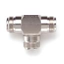 When combining the two sections of line, it's best to use a Tee connector with all female connections, like the one seen to the right. This way you can connect on your two phasing cables, then attach your transmission line directly to the harness. After you connect this up, remember to use
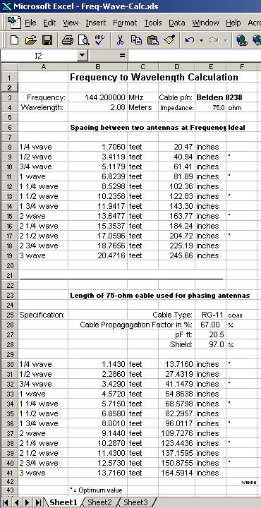 I made this chart using MS Excel, and it will also run on Sun Open Office. Here is the template.