Author: Frederick R. Vobbe, W8HDU
November 28, 2008 (updated: Feb 28, 2009)
| Antenna 015: The TTFD v1 Author: Frederick R. Vobbe, W8HDU November 28, 2008 (updated: Feb 28, 2009) |
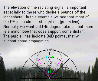
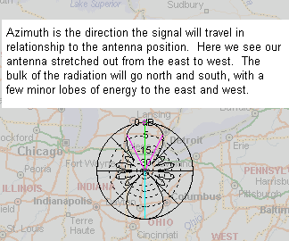
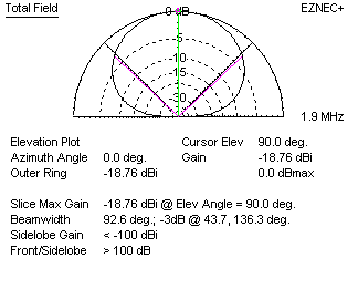
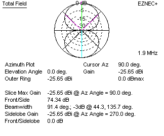
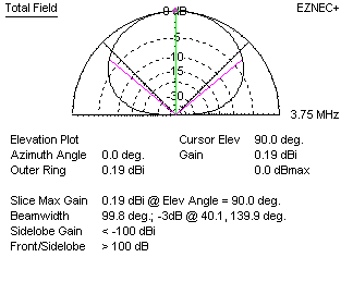
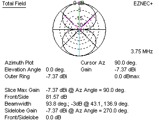
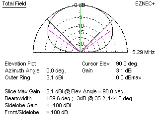
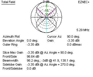
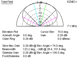
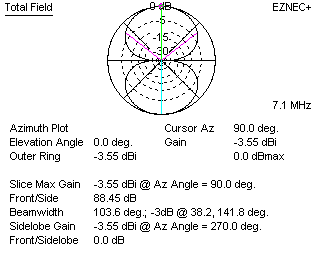
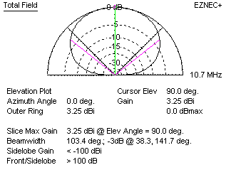
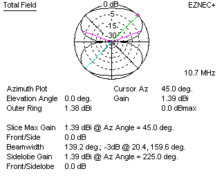
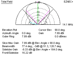
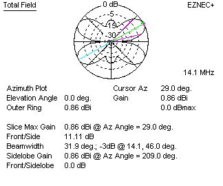
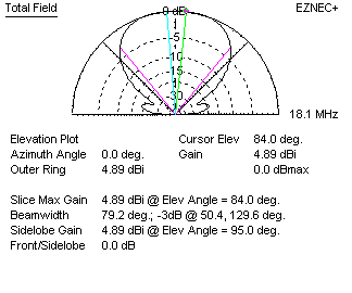
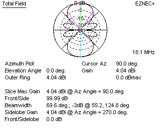
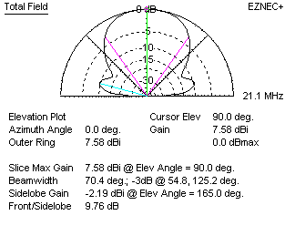
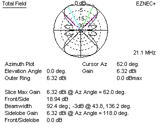
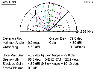
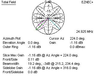
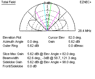
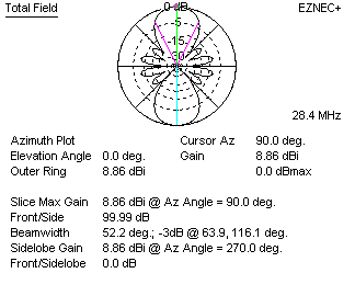
Of all the antennas I have built, my favorite is the Tilted Terminated Folded Dipole, or TTFD for short. The TTFD has been called a lot of "nice" names. A squashed rhombic, a folded-loaded dipole, inverted double-folded vee, and I've even heard it called an All Band antenna. This is one of two varieties of the Tilted Terminated Folded Dipole. It has also been called a lot of "bad" names because it's not understood too well, and most hams do not comprehend the matching of an antenna, therefore the impedance bumps in the TTFD frustrate them. I should point out that once I grasped the understanding of how this antenna works, I prefer it for operating. It's quiet, and a good "all purpose" antenna. For the SWL it's an excellent receive antenna that can be made with, or without the balun. 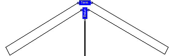 Figure 1 The reason it's called an all band antenna is because if it's carefully constructed and installed, this antenna will work well on all bands from 80 to 10 meters! I have been successful in a 160 meter version, but it also gets large and then the performance drops out on 20 to 10 meters. It also depends how high it's mounted, as there is an interaction with the earth. This antenna has been around for over 50 years. To my knowledge the design was first made public in 1949 in the ARRL's QST. If someone knows of earlier research, let me know! Later is showed up in a May 1984 edition of 73 Magazine. Arnie Coro, host of "Dxers Unlimited" on Radio Havana Cuba also writes about it on the www.radiohc.org web site. So it's far from being one of those mystery antennas. The United States Navy used this antenna during WW-II, and if you're ever in Columbus OH at near the Ohio State Office of Emergency Management, on the NW corner of The Ohio State University Airport, you'll see THREE of these antenna supported by 100' towers in a triangle. This impressive array is what they use for long range HF communications. The TTFD antennas are also available from two manufacturers at a rather premium price. The TTFD is a hard antenna to construct for some people. There is a lot of hardware, and it can be a little difficult to install without tangling wires. Another gripe of some hams is that it does not have the gain that other antennas have. I can not dispute this, but it's only a minor 2 dB loss, and I've never worked any station any other antenna that I couldn't work on the TTFD. However, here's what makes it excel over other antennas. It's the most quiet antenna that I've ever used. While I do have a 2 dB loss, I pick up 4 to 6 dB in lack of noise. This makes S1 signals good copy. And compared to a vertical it's well over 9 to 12 dB less noise. The TTFD is basically a closed loop antenna with a feed point on one side in the center, and a termination on the opposite side. The ends are then drooped down, giving it the name of the "tilted" terminated folding dipole. As you see in figure 1 above, we feed the antenna with a balun. The dipole ends go out, up, then back to the center where they are terminated with a non-inductive resistor. According to the articles I've read in many books about this antenna, there is a differing opinion as to the feed point design and the termination resistor value. Quickly, let me point out one thing on the termination. Any resistor you use for a termination must be non-inductive. Also, the rating for these resistors must be at least 25% greater than the peak power you will use. If you're using this antenna for receive only, a couple 1/8th watt carbon resistors are just fine. But if you're using this for transmitting, size the resistors wattage according to the maximum power you intend to run. 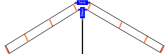 Figure 2 To keep the wires straight you can use some white 1/2" rigid PVC water pipe, and drill holes in the end as shown above in figure two. You will want to make sure you make all eight pieces exactly the same. For a spacing of 18" wire to wire, the pipe pieces should be 20" long. Drill a 1/8" hole about 1" from the end of the pipe. There are two ways you can attach the wires. Either pass the antenna wire through, and then attach a small few strands of wire around the pipe and attach to the wire to hold it in place. Or you can lay the wire next to the hole, and pass the strands through the hole to the wire, and wrap it around to hold the wire and pipe in place. Be sure that your support wires at the end of the antenna do not touch the antenna wires. Now, let's look at how this antenna reacts. Again, let me point out that this antenna is a reasonable solution to an "all band" antenna, however it's not perfect. Therefore you should be prepared to use some type of antenna tuning to take the edge off any VSWR artifacts. As you can see, the antenna's radiation pattern varies from band to band. One should consider this when building this antenna.
As I mentioned, this antenna's match will change as the frequency changes. Below, in figure 3, you'll see a our antenna. The length of "A" is 46 feet. The highest point of the antenna, "C" is 45 feet above ground, with the lowest tip of the antenna being 10 feet above ground. The spacing between wires, "B", is 18". We're assuming a 4:1 balun on the antenna fed via 75-ohm coax, and the termination resistor to be 390-ohms. 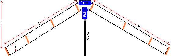 Figure 3 A sweep of 1.6 to 30.1 megahertz was performed at .25 megahertz steps, and below in figure 4 you see what the match would be. See why we need a tuner? 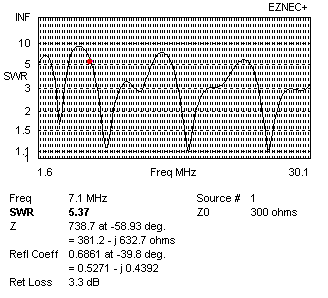 Note that the best case is at 25.6 mHz with a match of 1.0 : 1.13 or a 24.2dB return loss. Worse case is at 5.85 mHz with a match of 1.0 : 8.83 or a 2.0dB return loss. This is why many users of these antennas will construct the antenna with open feeder line going to a tuner. It's much easier to tune this antenna in this manor. One final note, as you droop the wires down, you may have to take in some slack on the bottom wire. Looking at the wires from the side they arrange into a Trapezoid. To make this antenna mechanically perfect, I usually put small aluminum turnbuckles on the load, and jumper over them with copper wire. This allow me to tension the top and bottom wires evenly which helps the structural integrity of the antenna. Changing the length does cause a varience in matching, but not so much of a change that it rules out use of the antenna. Frederick R. Vobbe, W8HDU |
 |
© Copyright 2012 All Rights Reserved - W8HDU |